Cd4008 4-bit full adder ic pinout, working, example and datasheet Adder carry sum circuit logic simplified implementation electronics output outputs two tutorial circuits combinational both shows below figure Edacafe: power, accuracy and noise aspects in cmos mixed-signal
Digital Electronics Part I : Combinational Circuits
Adder figure diagram Hands-on: building a full adder • egomachines Adder combinational electronics circuits constructed wider adders
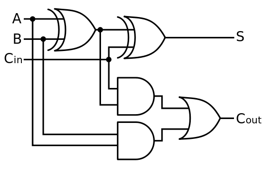
Full adder
Half adder circuit: theory, truth table & constructionFull adder circuit: theory, truth table & construction Adder circuit logic gates xor hardware schematic hands building assemble wellAdder circuit construction binary circuits ibm sourav gupta.
Adder cmos circuit diagram fa transistor using 28t transistors implementation edacafe transmission gate power fig www10 phdthesis bookAdder datasheet xor inputs Figure 1: schemaric of a full adderDigital electronics part i : combinational circuits.

Adder half circuit diagram ic ics pinout construction its gate truth table input both bit gates sites circuitdigest below dc
Circuit diagram of a one-bit full adder using the proposed technique inAdder cmos soi .
.


EDACafe: Power, accuracy and noise aspects in CMOS mixed-signal
CD4008 4-Bit Full ADDER IC pinout, working, example and datasheet

Digital Electronics Part I : Combinational Circuits

Hands-on: building a Full Adder • EgoMachines

Figure 1: Schemaric of a Full Adder

Half Adder Circuit: Theory, Truth Table & Construction

Circuit diagram of a one-bit full adder using the proposed technique in